
8.04 Angles and constructions
Introduction
We saw the use of properties of angles to solve problems in 7th grade. This lesson will discuss prior ideas and vocabulary, and then extend our use of angles to the construction of angles using various methods.
Using properties of angles to solve problems
There are two postulates that allow us to measure and solve problems with angles.


The angle addition postulate only works for adjacent angles, or angles that share a common leg and vertex, but do not overlap.
The measure of an angle is defined using the protractor postulate.


The linear pair postulate states that if two angles form a linear pair, then they are supplementary, which means the sum of their angles is 180\degree.

Exploration
Check the box to 'show reflex angle' and drag point A to change the measure of the angle.
- Create the following types of angles and observe the reflex angle: right, acute, obtuse, straight.
- What do you notice about each reflex angle?
Angles can be classified based on their measure:


Examples
Example 1
Solve for x.

Example 2
Consider the diagram, where m \angle PQR = 145 \degree.

Write an equation and solve for x.
Find m\angle{SQR}.
Example 3
The angles in the diagram are complementary. Find the value of x.

Example 4
Use the diagram to identify an example of each angle pair.

Vertical angles
Linear pair
We can use protractors and algebra to measure angles and solve problems involving angles. We can use definitions and postulates for supplementary, complementary, vertical, and adjacent angles to solve problems.
Angle constructions
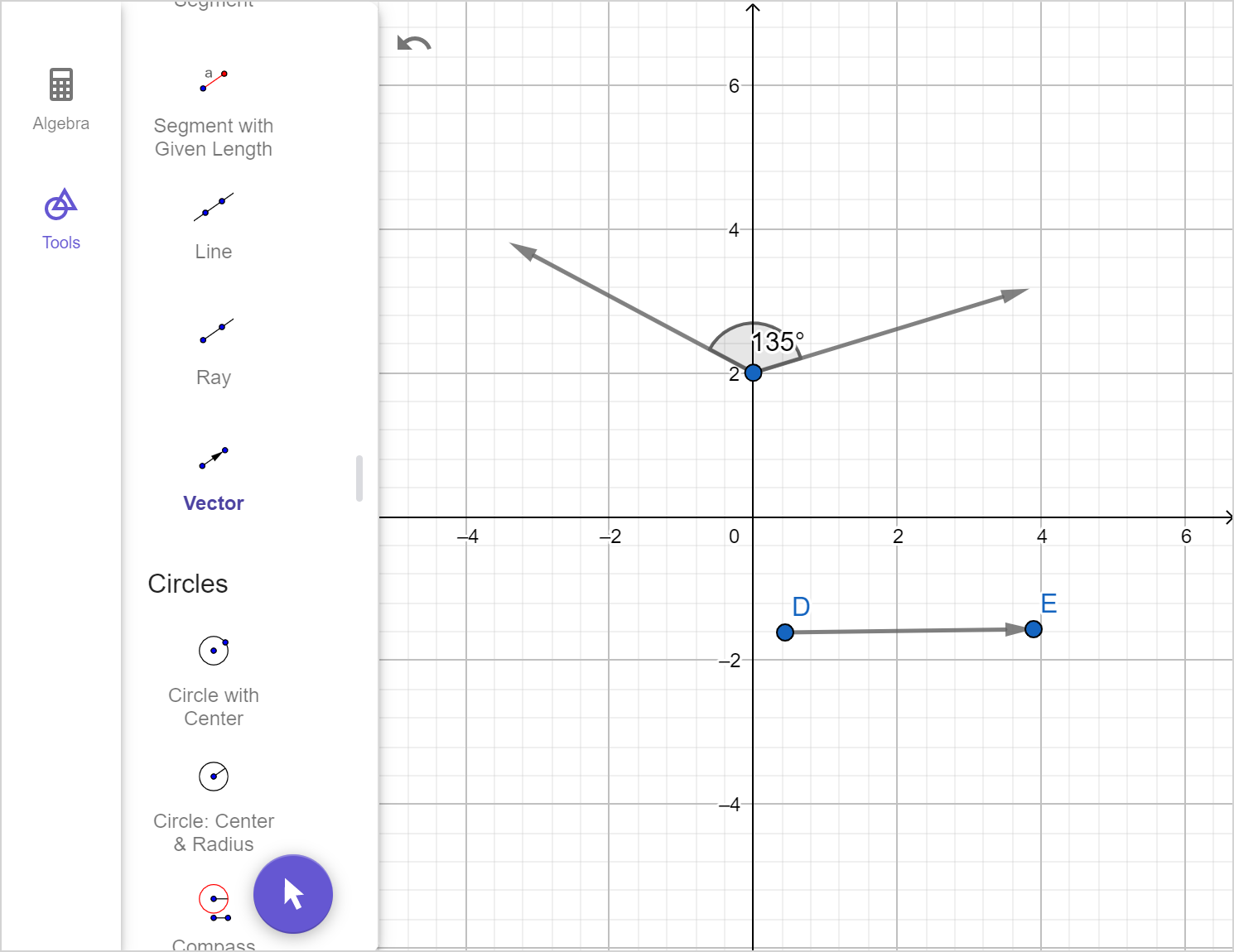
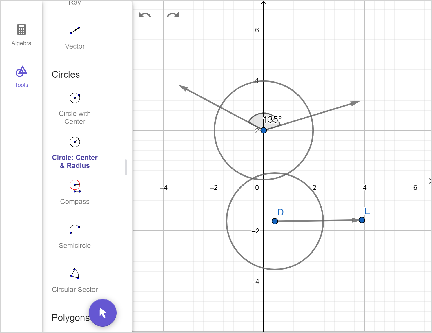
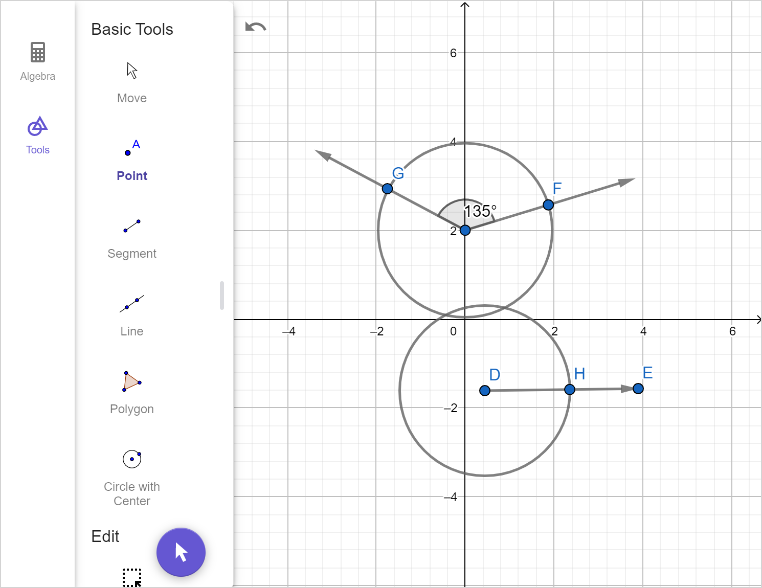
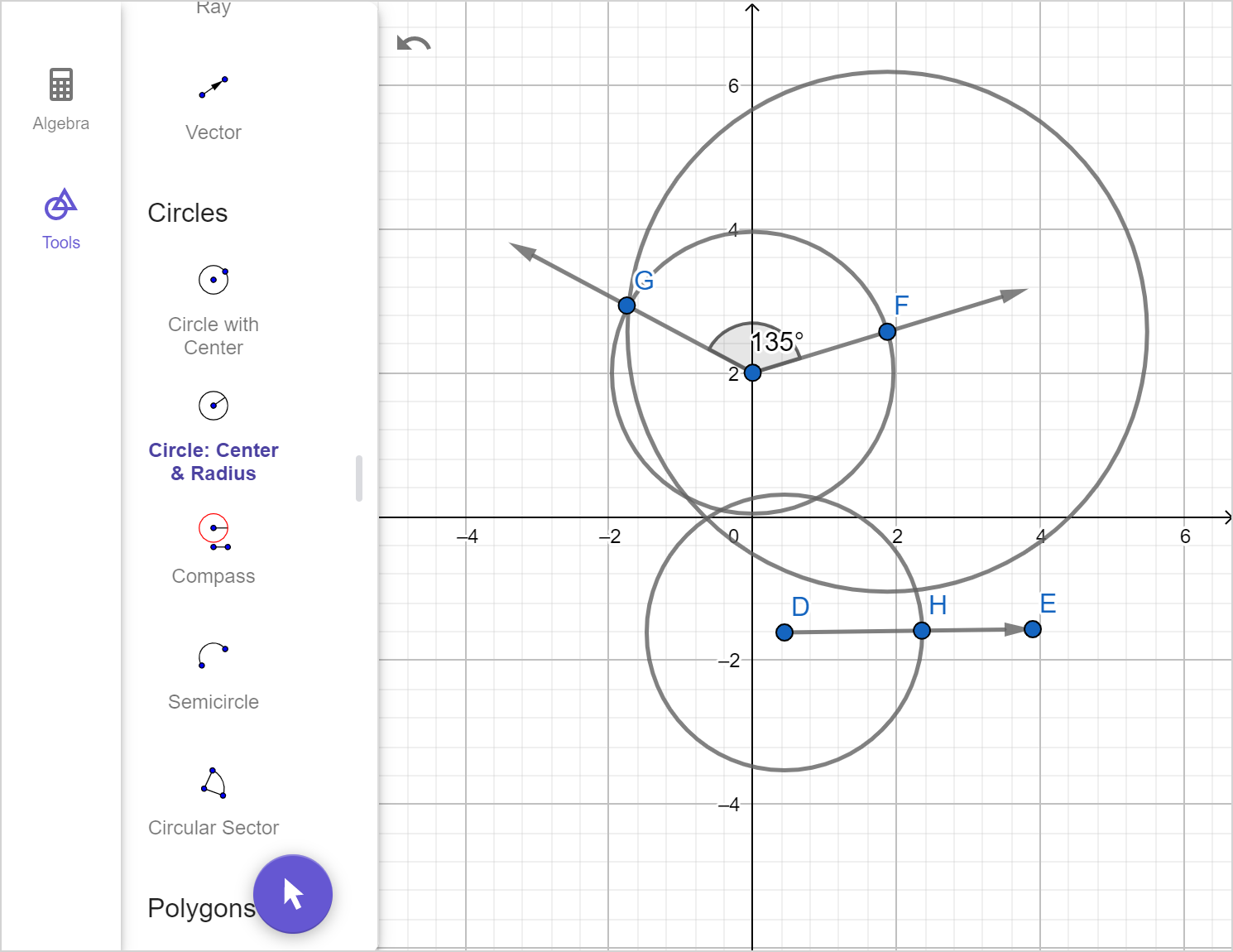
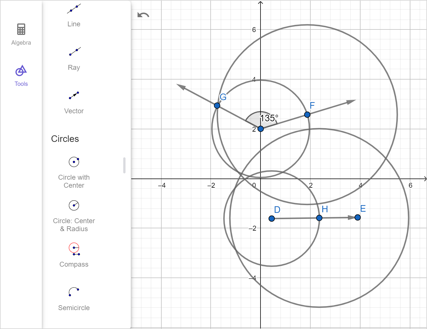
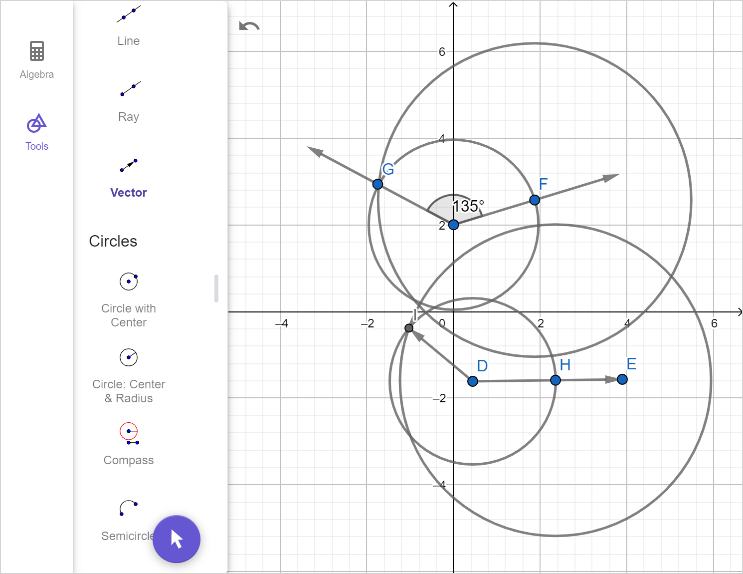
Exploration
Use the 'Next' arrows to view the construction.
- Describe what is happening at each step of the construction.
To construct a copy of an angle, we will:
- Identify the angle we want to copy.
- Draw a ray that will form one of the legs of the copied angle.
- With the compass point on the vertex of the original angle, use the compass to draw an arc that intersects both legs.
- Copy the arc in Step 3 by placing the point end of the compass onto the endpoint of the ray.
- On the original angle, use the compass to measure the distance between the points where the legs of the angle meets the arc drawn in Step 3.
- Without changing the compass width, copy the distance by placing the compass point where the ray meets the copied arc and draw an intersecting arc.
- Draw a ray that shares its end point with the ray from Step 2, and goes through the intersection found in Step 6.

To construct the bisector of an angle, we will:
- Identify the angle we want to bisect.
- With the compass point on the vertex of the angle, use the compass to draw an arc that intersects both legs.
- Label the intersections with points.
- With the compass point on one of the points from Step 3, draw an arc that passes halfway through the interior of the angle.
- With the compass point on the other point from Step 3, draw an arc that passes halfway through the interior of the angle and intersects the first arc.
- Label the intersection of the arcs drawn in parts 4 and 5 with a point.
- Draw a line that connects the vertex of the angle and the point added in Step 6.

Examples
Example 5
Construct a copy of the angle shown.

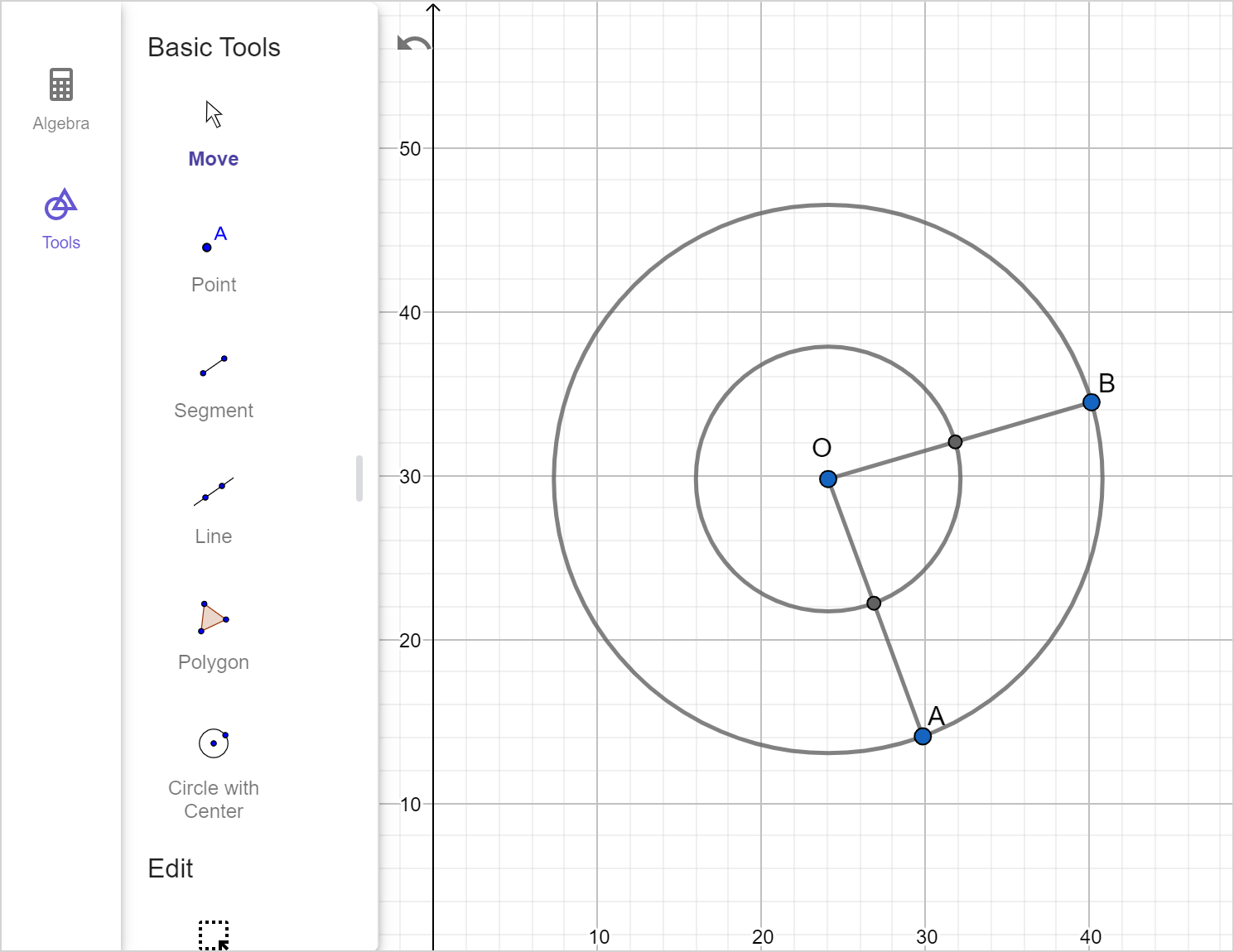
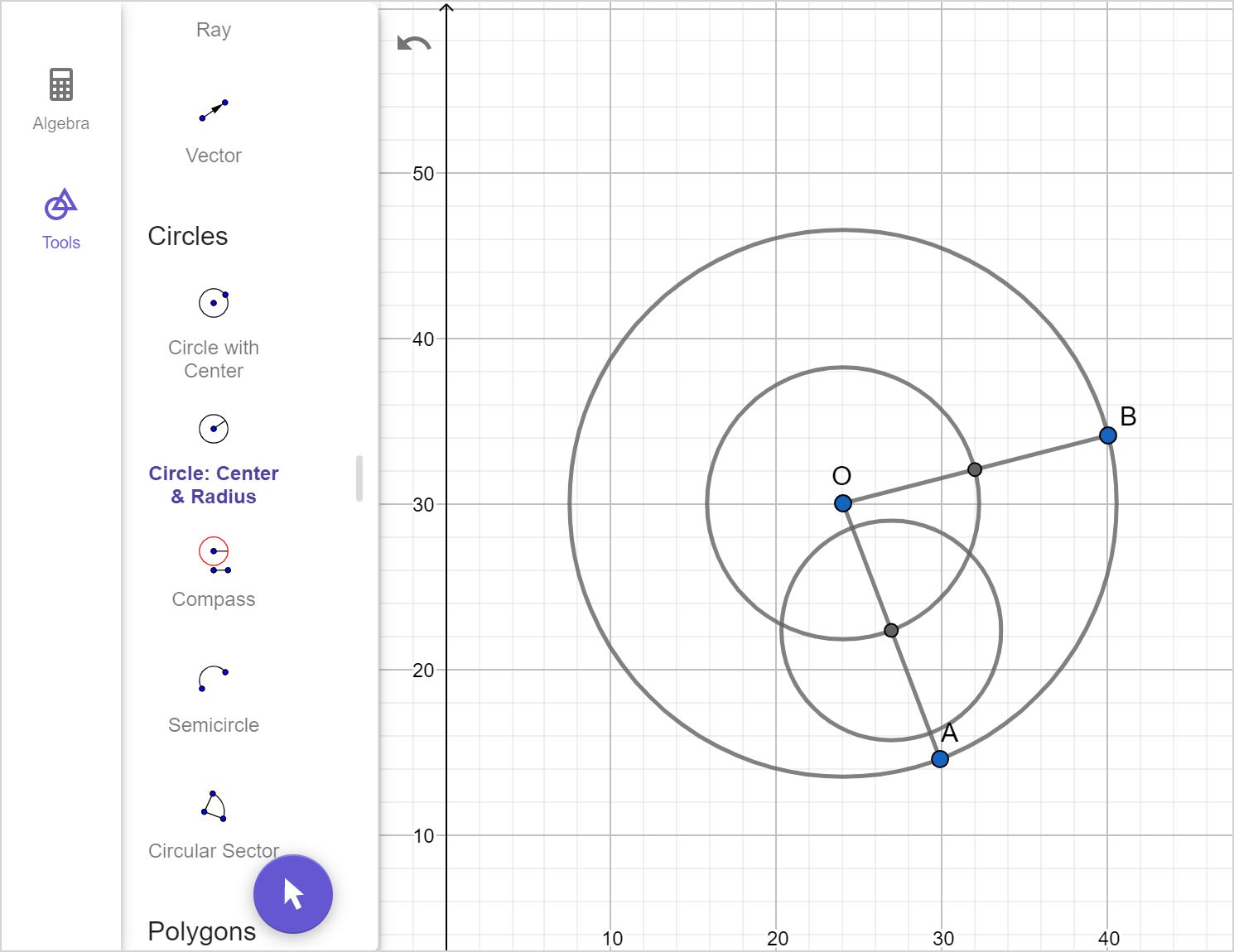
Example 6
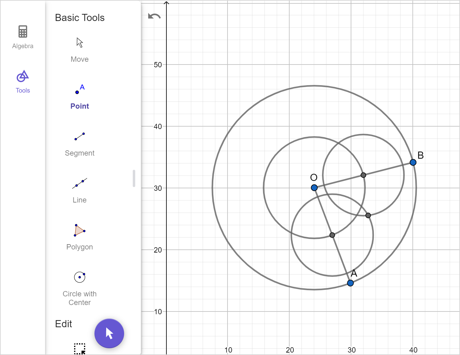
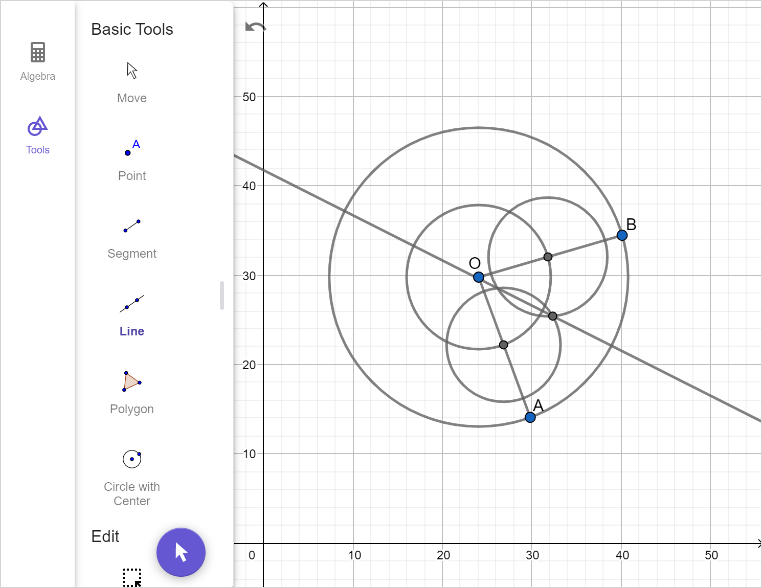
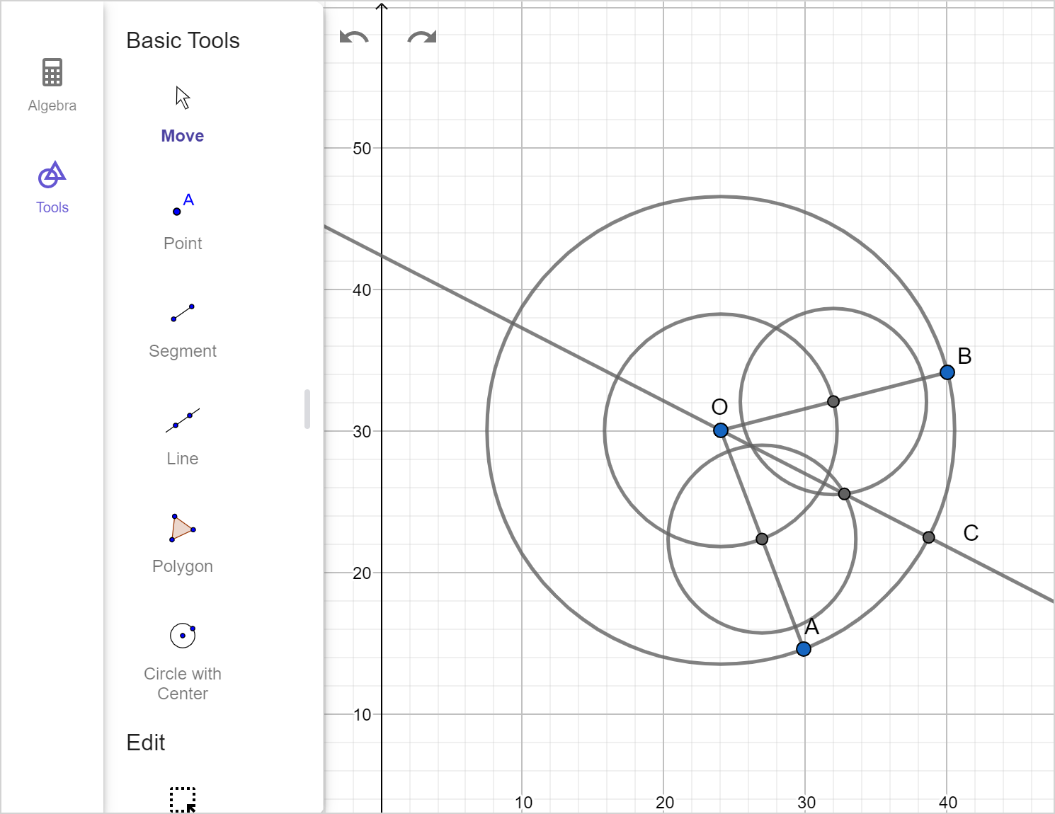
A circle centered at O has radii \overline{AO} and \overline{BO} as shown.

Find and label point C, which lies at the midpoint of minor arc \overset{\large\frown}{AB}.


A compass and straightedge can be used to construct angles as well as the use of technology or string.